Mechanical Design • CNC Machining • Systems

Supercritical CO2 Turbine Generator

A turbine-generator assembly supporting high speed rotor-shaft rotation from high temperature and pressure supercritical CO2 Rankine cycle to generate electricity.

SolidWorks GD&T DFM CNC Mill CNC Lathe Wire EDM Fusion360 Cam
Previous image preview Main slider image Next image preview

Project Overview

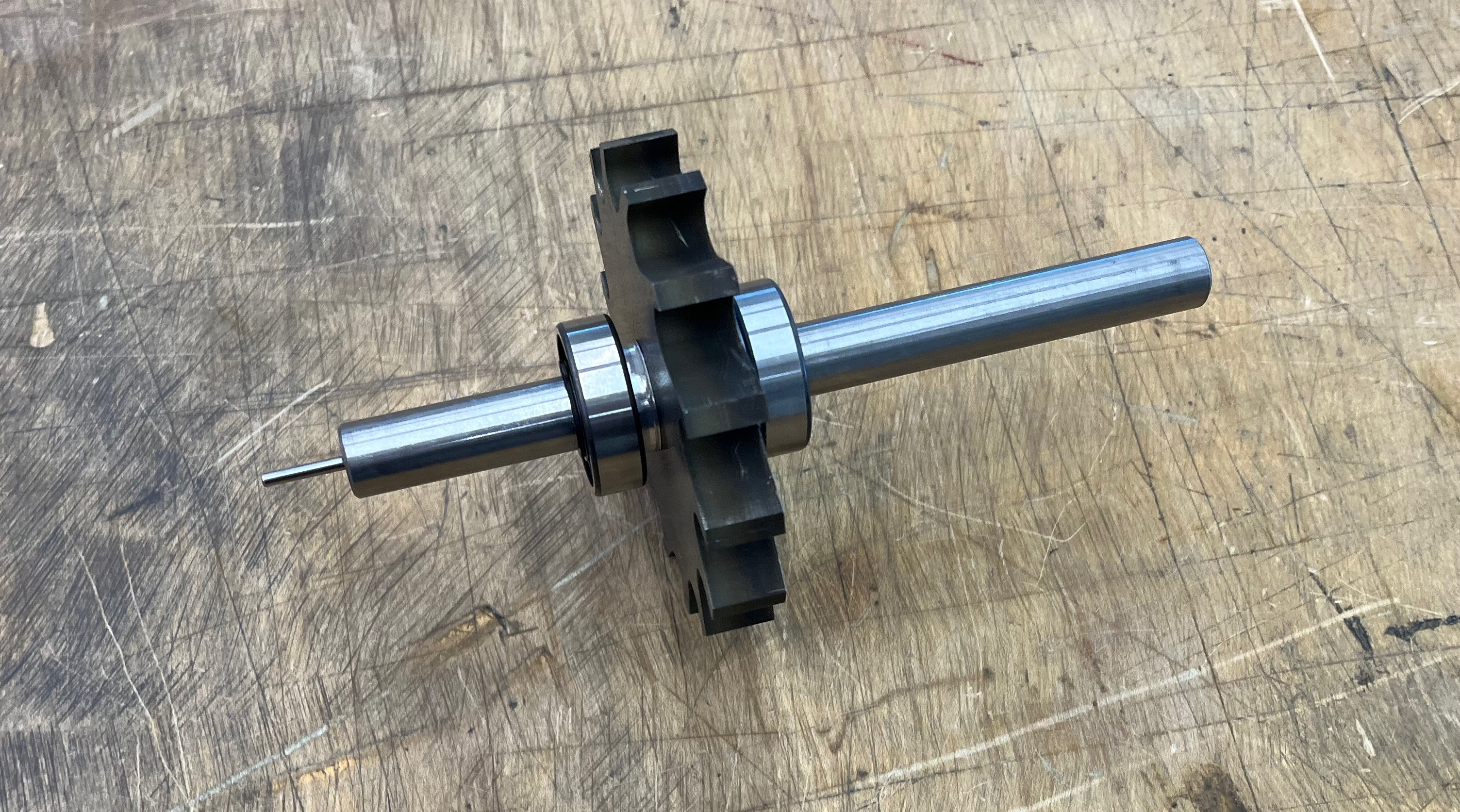
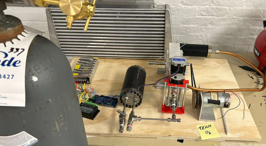
The turbine converts thermal energy from supercritical CO₂ into mechanical and electrical power. A sealed enclosure with endcaps, O-rings, and shaft seals maintains the high-pressure flow, while a Pelton-style rotor spins up to 30,000 RPM on ball bearings. A nozzle accelerates the CO₂ into a high-velocity jet that drives the rotor and shaft. The system follows a Rankine cycle: CO₂ flows from a tank to an evaporator, expands through the turbine, and is then condensed.

What I Worked On

  • Designed all turbine components on SolidWorks for manufacturability, effective rotation, and sealing integration.
  • Prepared CNC setups and performed machinging operations for all turbine components
  • Specified materials and components to meet RPM requirements and operating conditions.
  • Created detailed technical drawings and tolerance stack-ups to ensure machining accuracy.
Previous image preview Main slider image Next image preview

GD&T and SolidWorks

All turbine components were defined using GD&T to ensure proper fit, sealing, and alignment at high speeds. Parts were designed in SolidWorks with clear dimensioning for accurate machining and assembly.

Section views highlighted O-ring sealing and the keyed rotor-shaft connection, guiding CNC manufacturing and ensuring consistency.

Mechanical Design

Component Highlights

Previous image preview Main slider image Next image preview

Enclosure

The aluminum enclosure was machined in the CNC Mill and serves as the static housing for the spinning rotor.

Previous image preview Main slider image Next image preview

End Caps

Circular aluminum stock was faced, bored, and drilled to create the end caps on the CNC Mill with Fusion360 Cam.

Previous image preview Main slider image Next image preview

Rotor

The steel rotor was first cut with precision in the wire EDM to optimize concentricity and cut square key hole. The rotor was then faced in the CNC mill.

Build Process

Machining Highlights

CNC Mill

3-axis CNC milling was used to machine the enclosure, end caps, and flat components, including facing, pocketing, and drilling operations.

CNC Lathe

The CNC lathe was used to machine cylindrical features such as the shaft and nozzle, ensuring concentricity and precise fits for rotating components.

Wire EDM

Wire EDM was used to cut the rotor profile and keyway with high precision, maintaining tight tolerances and sharp internal features.

What I Learned & Future Improvements

This project improved my ability to design for manufacturability and strengthened my CNC machining skills. I worked through the full process from CAD to assembly, seeing how design decisions impact fabrication and fit. Moving forward, I would focus more on tolerances during machining to reduce post-processing and improve efficiency.

Contact Me

Feel free to reach out for projects, collaboration, or opportunities.