Analysis • Prototyping • Testing

Balancing Car

Motorized wheel control project focused on acceleration control to balance a one foot aluminum extrusion.

SolidWorks Motion Study 3D Printing Arduino Laser Cutting
Previous image preview
Next image preview

Project Overview

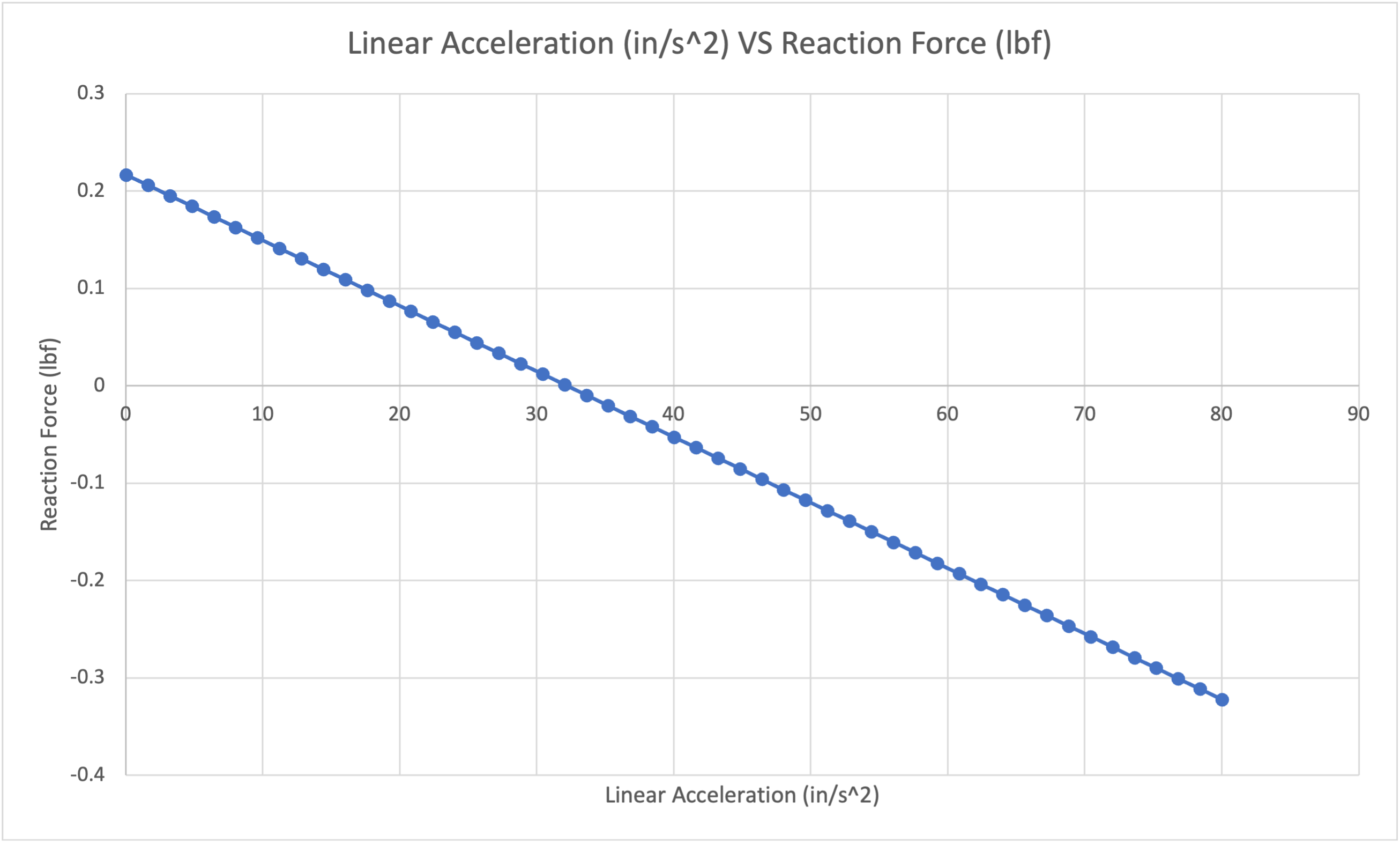
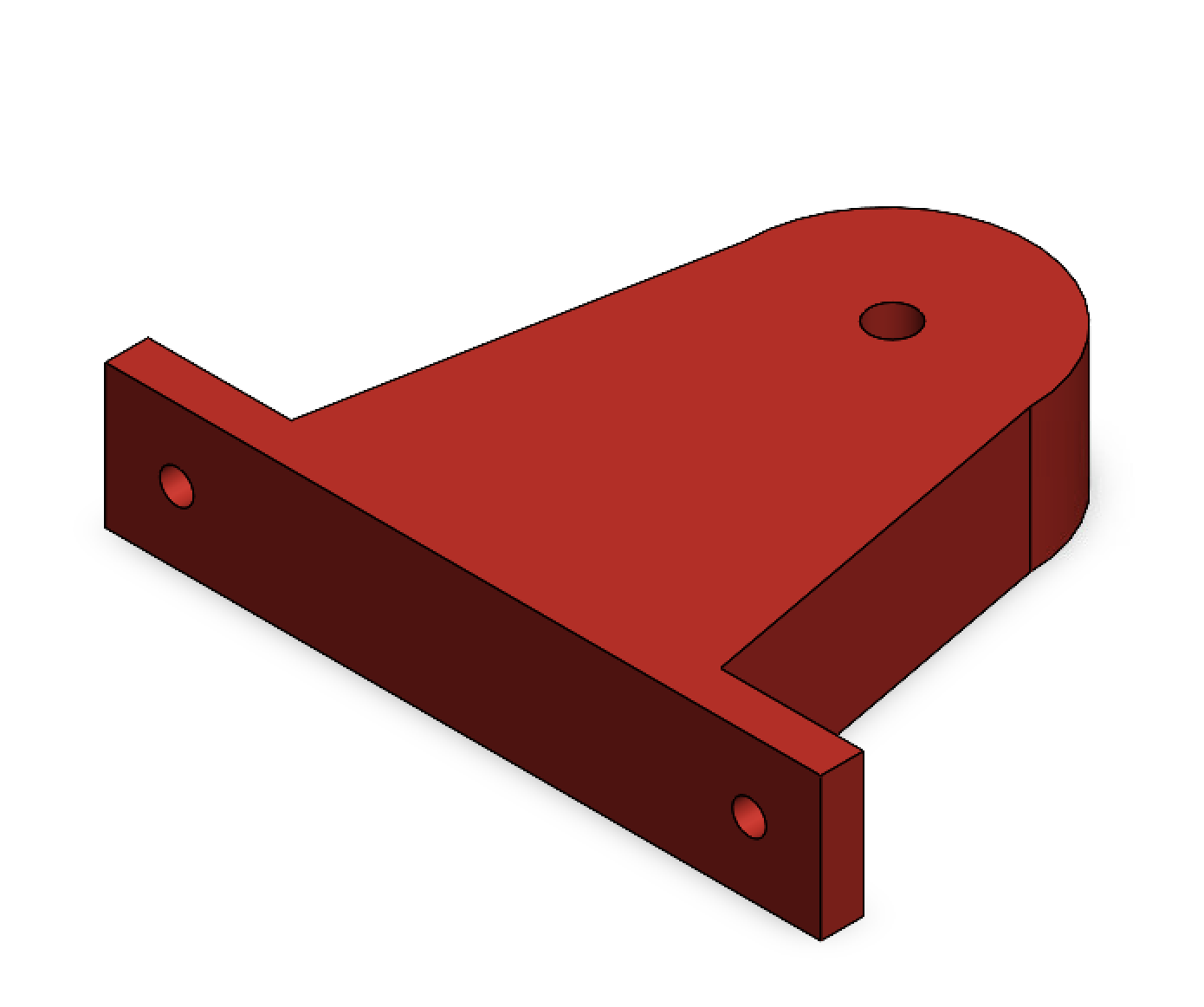
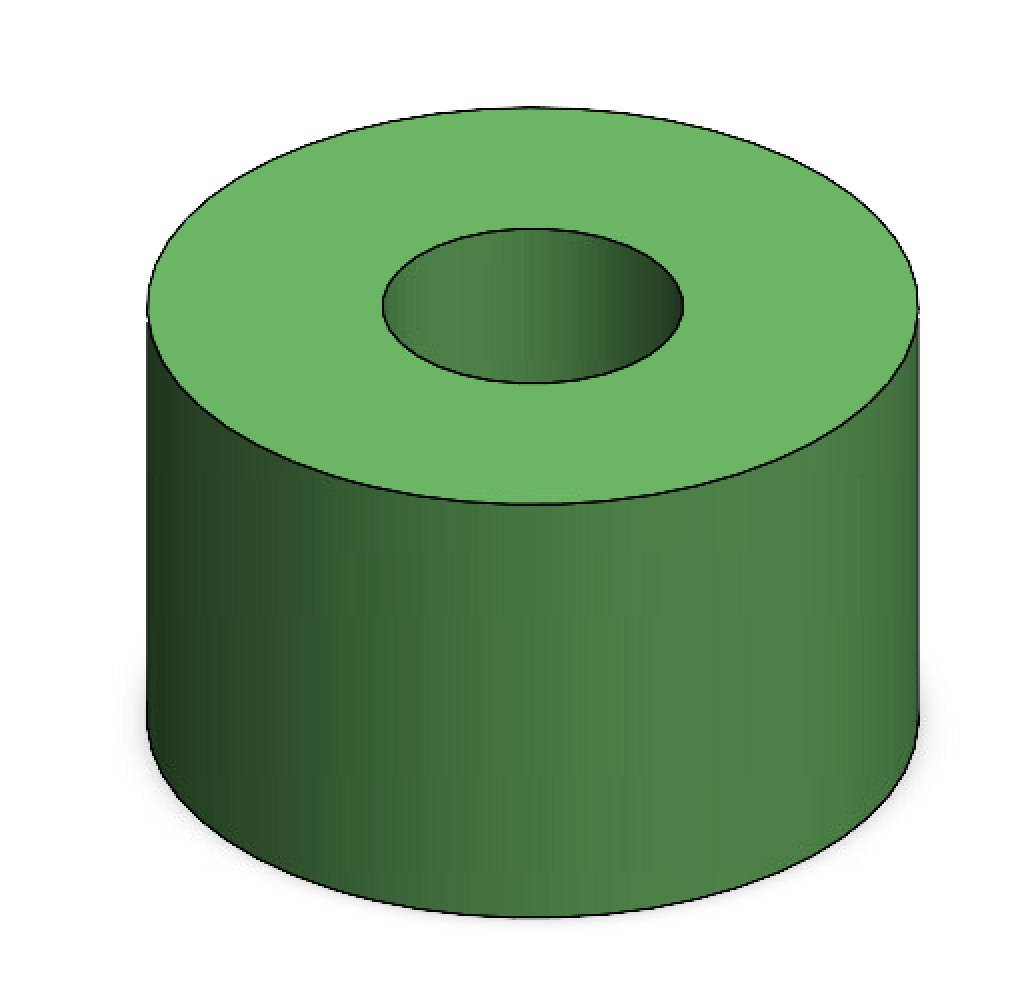
This project focused on designing a balancing car platform with custom wheel geometry to support a one-foot aluminum extrusion. Motion analysis was used to optimize load capacity and stability, followed by physical assembly and testing of the drive system. The final system was evaluated on its ability to travel a set distance as quickly and reliably as possible, balancing speed, stability, and structural performance.

What I Worked On

  • Determined optinized wheel size based on motor speed and analyized max acceleration extrusion could balance with
  • Laser cut and 3D printed parts for efficient wheel motion
  • Generated code for car to accerlerate and decelerate to an exact diatance

Distance Test

The system was tested to evaluate distance control and stability under acceleration and deceleration. The car was able to travel close to the target distance consistently while maintaining balance of the vertical extrusion. Controlled acceleration and deceleration profiles prevented tipping, demonstrating reliable motion control and stable system performance.

End cap components

Acceleration Motion Analysis

This stage focused on determining the maximum allowable acceleration while maintaining system stability. Acceleration was increased until the reaction force at the back of the extrusion approached zero, defining the tipping threshold.

This relationship between acceleration and reaction force established a safe operating limit for motion. The final acceleration profile was selected to remain below this threshold, ensuring stable movement without compromising speed or performance.

Mechanical Design

Component Highlights

Previous image preview
Next image preview

Wheel

The wheel design diameter was determined based on the max motor speed to reach desired max acceleration.

End cap components

Axle Support

Custom supports were designed to mount the axle and integrate the wheel system with the platform structure.

End cap components

Spacers

Spacers were used to reduce contact and friction between rotating components, improving alignment and motion efficiency.

Assebmbly Design

System Highlights

Previous image preview
Next image preview

Final Build

The integrated system combined motor control, structural components, and electronics into a compact platform for controlled motion and testing.

Previous image preview
Next image preview

Original CAD

The final build evolved from the initial CAD design, with modifications particularly in the wheels to improve performance from redesign.

What I Learned & Future Improvements

This project strengthened my understanding of how acceleration directly affects force in a real, hands-on system. Testing and iteration helped connect theoretical motion analysis to physical performance and system stability. A key improvement would be integrating a buck-boost converter to maintain consistent voltage and improve motor performance. Additionally, I would enhance the aesthetics through a more creative enclosure and refined wheel design to better integrate the system visually.

Contact Me

Feel free to reach out for projects, collaboration, or opportunities.